Southern
Pacific
1218
Turbosupercharger Repair
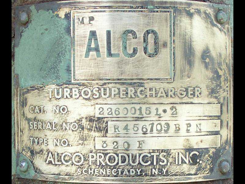
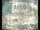
Our
Alco 6 cylinder model 251 is
equipped with a Alco model 320 turbosupercharger, the function of which
is to supply the engine with a high volume of air to be mixed with fuel
in the combustion chamber. The turbo makes the engine more
efficient and since it is driven by the exhaust gases, does not put any
mechanical drag on the engine like a supercharger.
 |
When we
eventually got the engine running, we found that the turbo made a
rather distressing noise, much like the sound of playing cards in
bicycle spokes. In addition to the racket, it would not speed
up
as it should and the engine smoked badly with the throttle above run
3. I made a recording of the noise which can be found at this link.
I made contact with
Globe Turbocharger Specialties in Reno, Nevada who advertise that they
rebuild the model 320 turbo. They said that they had never
heard
a noise like this but said they would help with our little
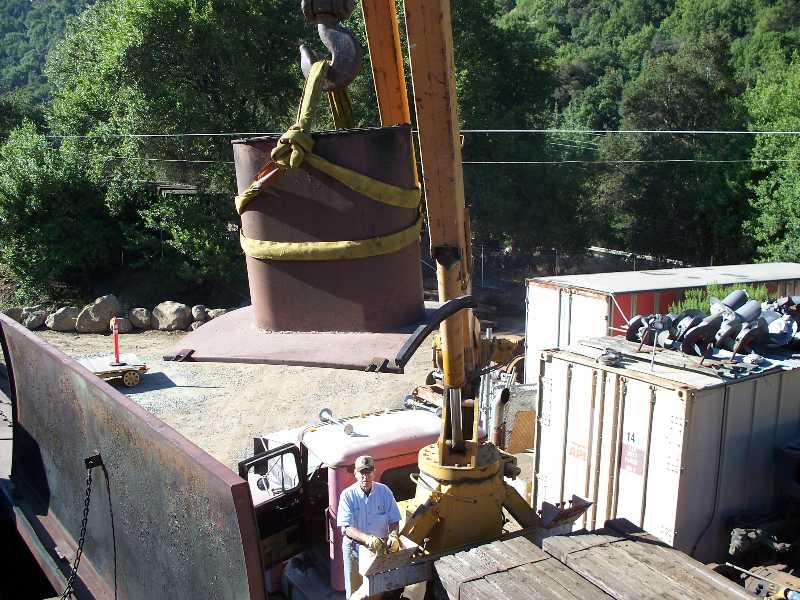
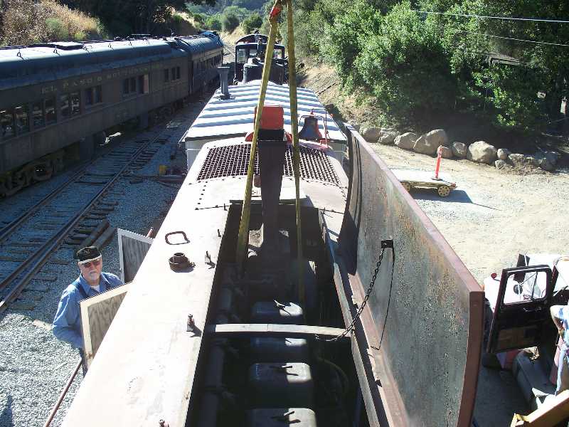
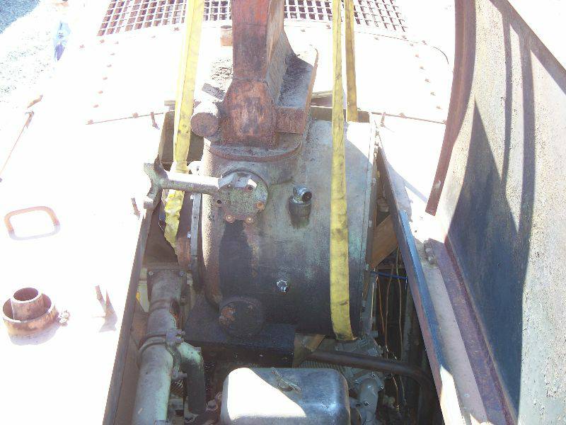
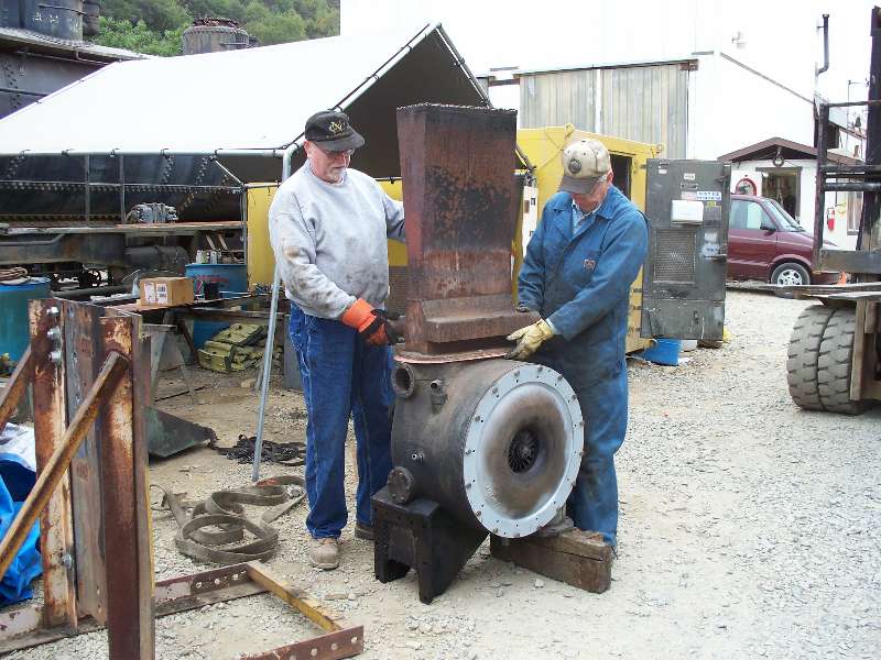
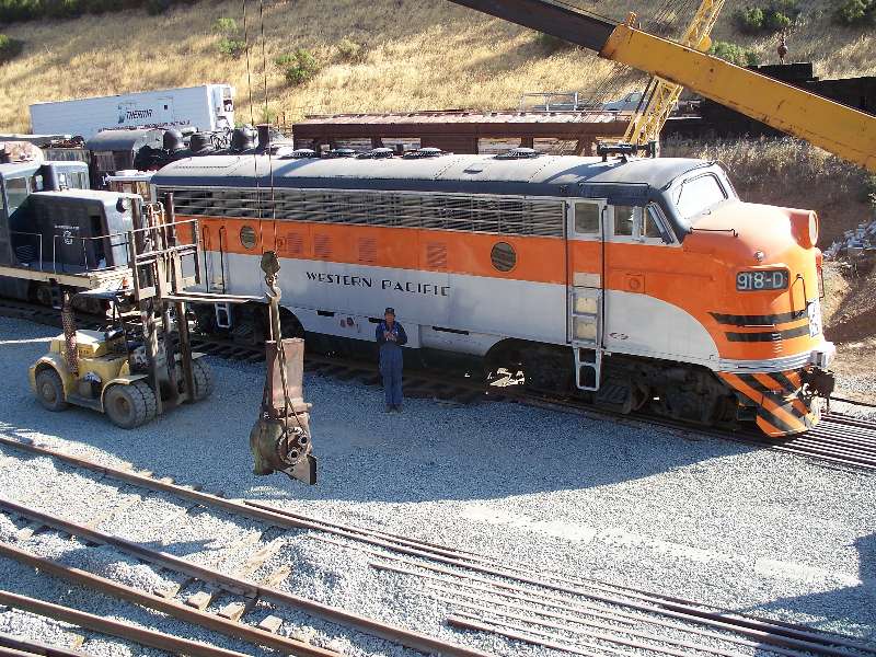
project. In order to pull the turbo, a
small roof
hatch, which includes the exhaust stack surround, was
removed. After removing the air filters and
connections to
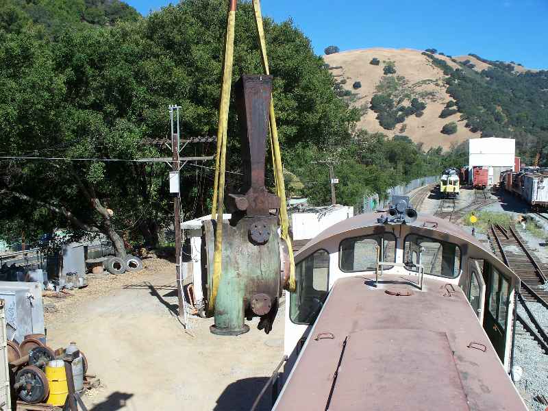
water, oil, exhaust and inlet, the 1200 pound turbo was
lifted
out of the locomotive.
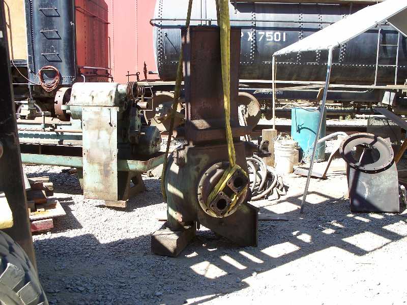
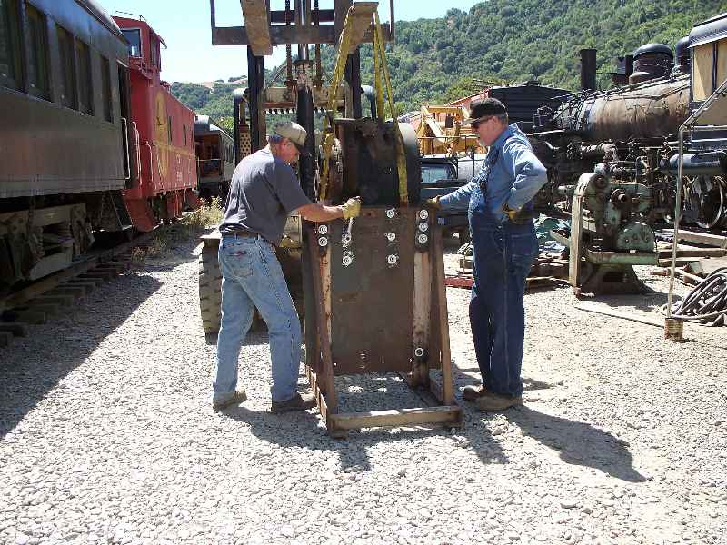
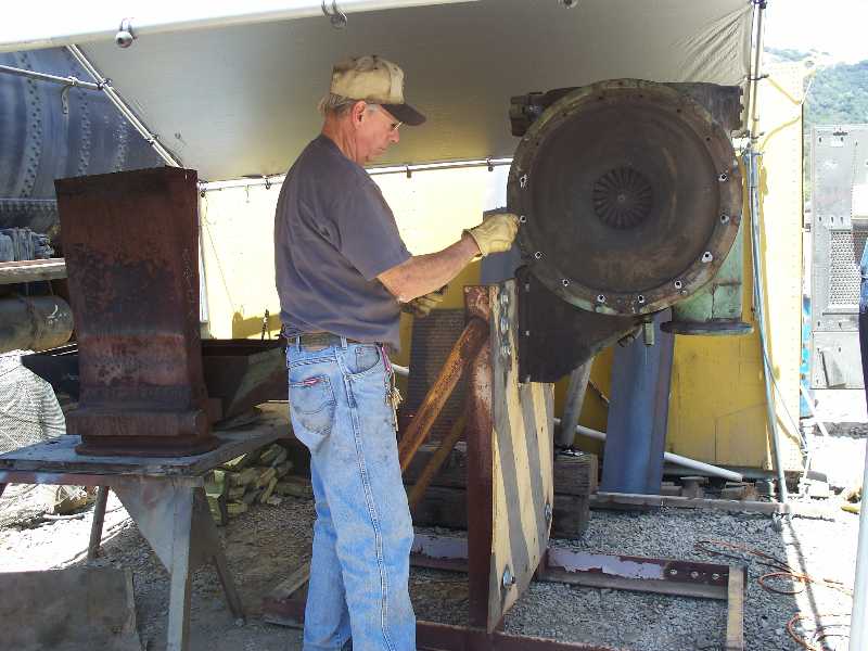
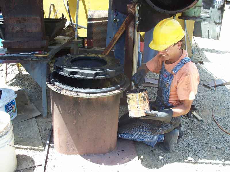
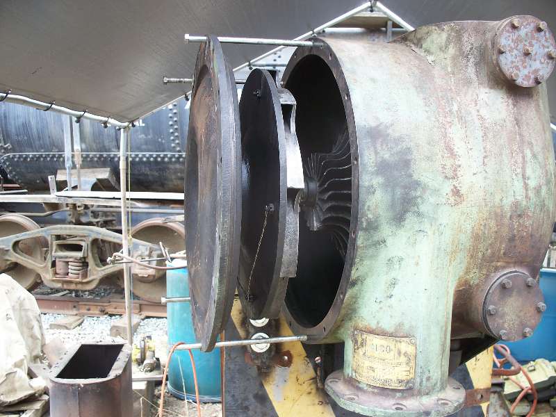
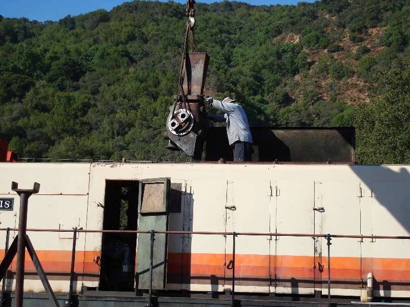
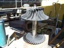
Once out of the
locomotive, the turbo was mounted on a stand made from angle
iron
and a piece of the front end of the 1218 that we had
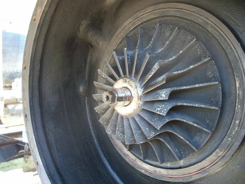
replaced. Rich is seen removing the ring
of bolts
from the air inlet casing that surrounds the inducer and
impeller. The two fans form the compressor which sends air to
the
engine.
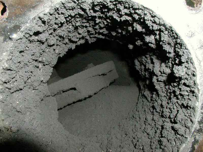
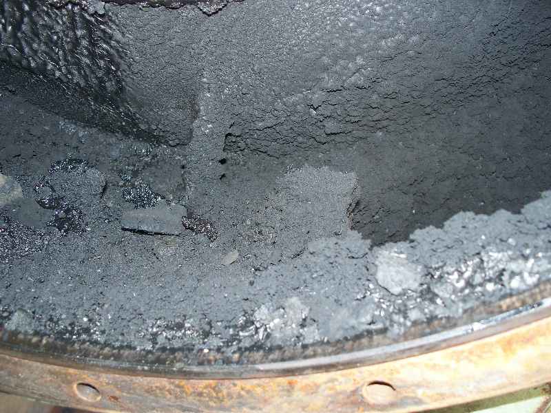
Upon removing the
casing, we discovered the reason for
the problems with the turbo. It was full of greasy crap and
carbon.
The air passages were almost completely plugged.
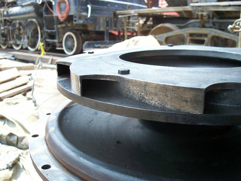
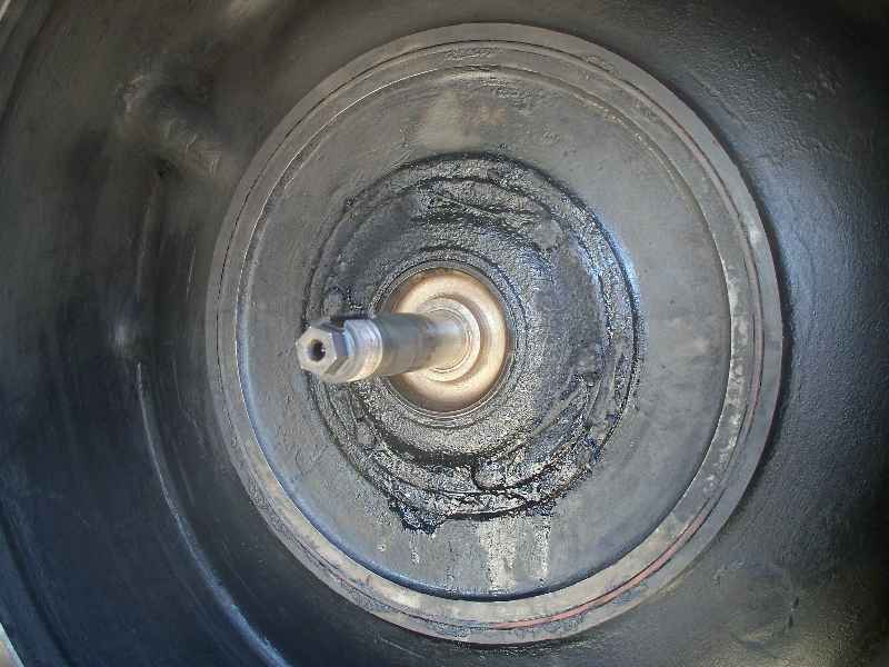
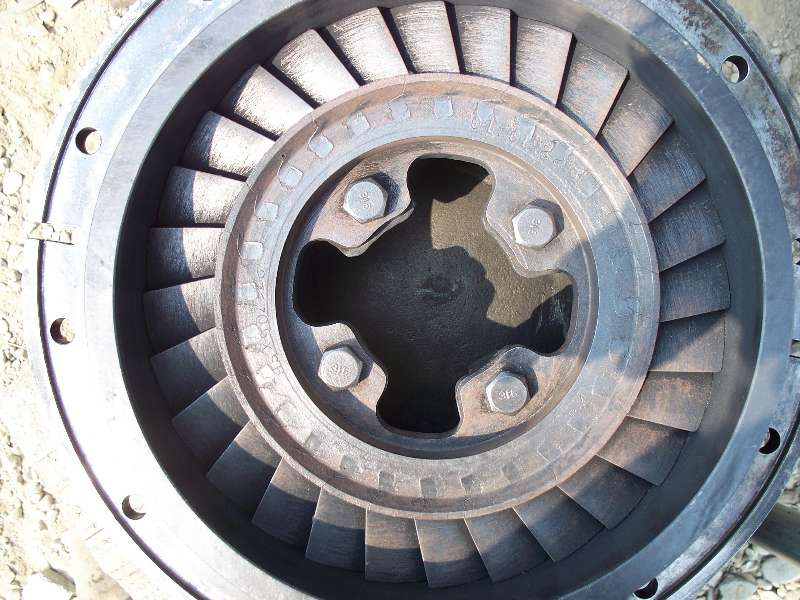
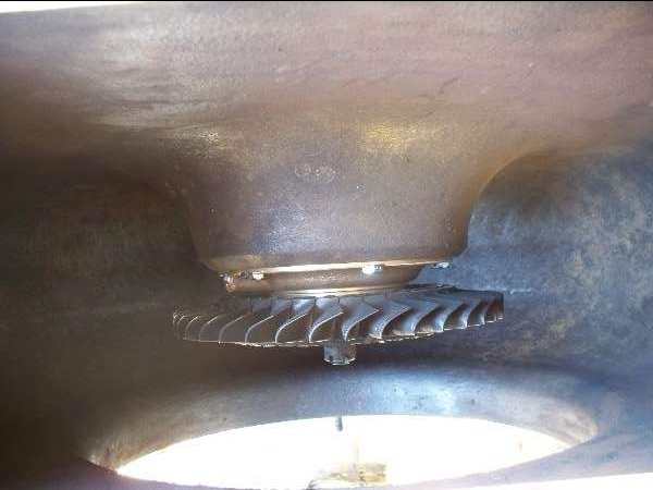
Photo 1 is
looking into the air chamber where it exits from the turbo.
The
slotted thing in the center of the opening is the diffuser where the
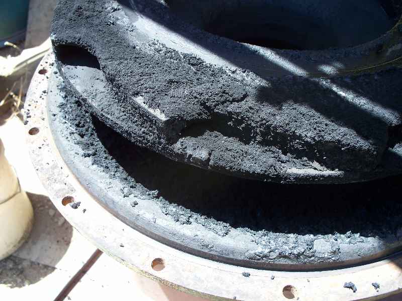
air is discharged from the impeller. Photo 2 is
of the air inlet casing itself. Photo 3 is a close-up of the
diffuser showing the nearly completely plugged air discharge
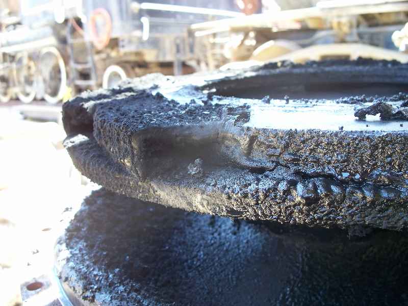
passages. Photo 4 is the same as photo 3 after the crud had
been
cleaned out of the chambers. Photo 5 is the inside of the air
chamber in the main turbo casting. And, photo 6 is of a happy
Jeff Coker who truly loves to clean things and is darn good at it.
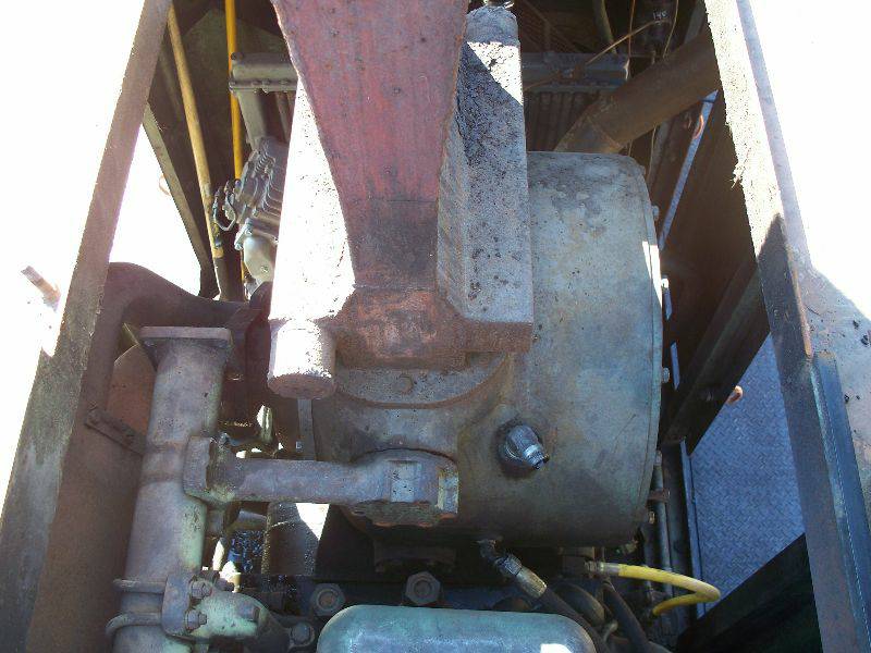
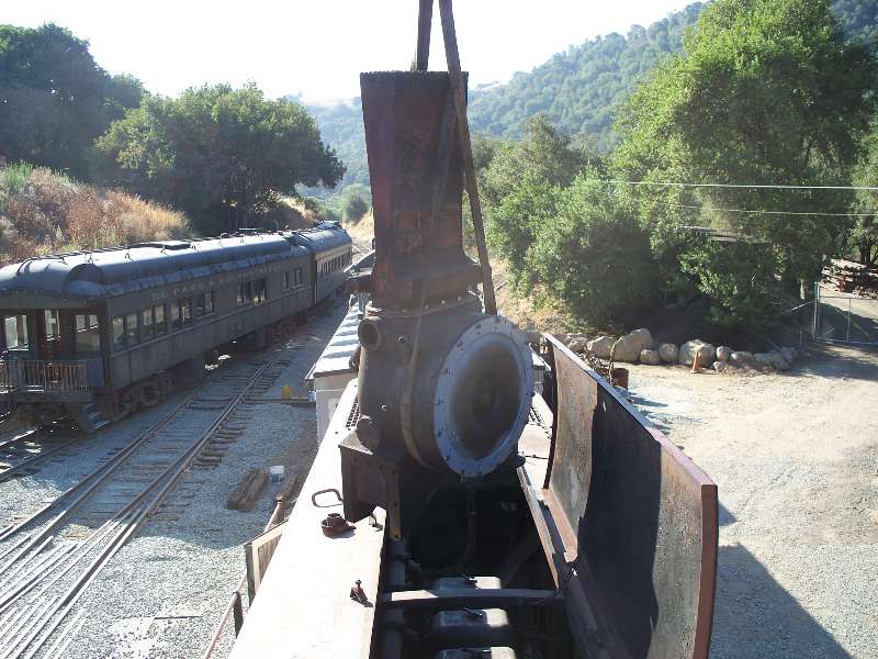
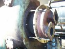
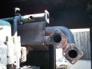
The
next step was
removing the gas inlet casing. This is the casting that
connects
to the engine exhaust and directs the exhaust to the turbine which
spins the shaft driving the impeller. The second photo shows
the
exhaust connections in the locomotive.
 |
|
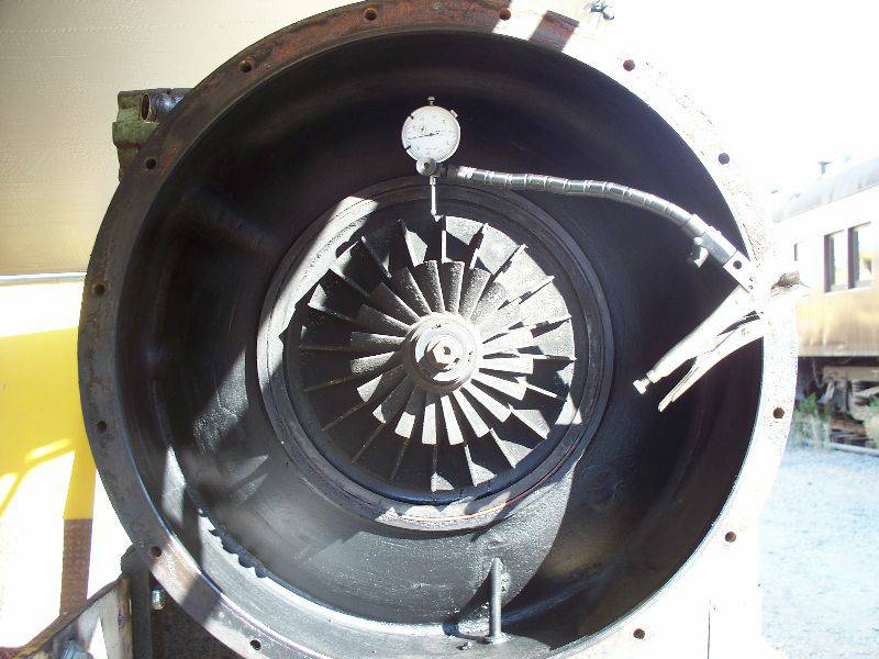
Once the casings
were out of the way, I could make some measurements to determine the
amount of wear in the turbo bearings. The dial indicator
indicated (?) that the shaft radial clearance was .008 (8
thousands). The specifications call for a minimum of .005 and
a
maximum of .009 so the wear was actually within tolerance.
The
other critical measurement is the amount of end play in the
shaft.
The specifications call for a minimum of .007 and a maximum of
.016. Our shafts moves .014 so this measurement was also
within
tolerance. But, given that the measurements are at the upper
end
of the limits and the air side bearing is damaged, we are changing the
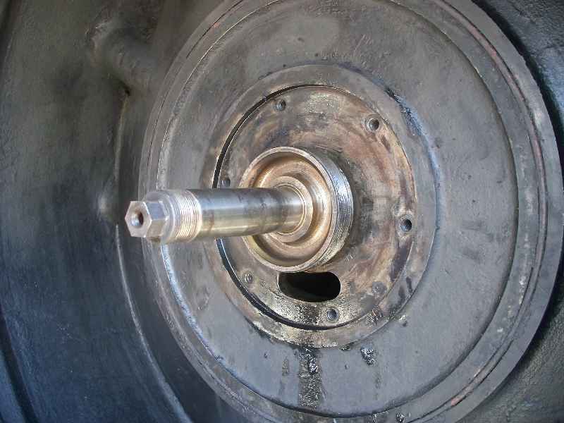
bearings and will adjust the end play. Photo 2 shows the
inducer
and impeller that forces air into the engine. It looks like
one
part but it is actually 2 aluminum castings slid on the
shaft.
Photo 3 is of the air side oil seal and photo 4 is of the air side oil
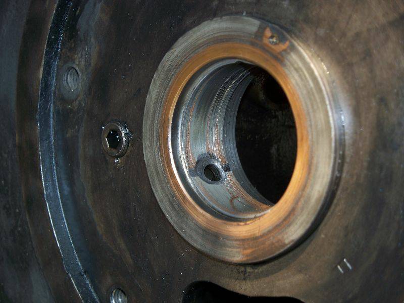
slinger which sits inside the seal. Photo 5 shows scoring on
the
surface of the air side bearing. This was likely caused by
dirt
in the oil which fortunately, did not affect the shaft.
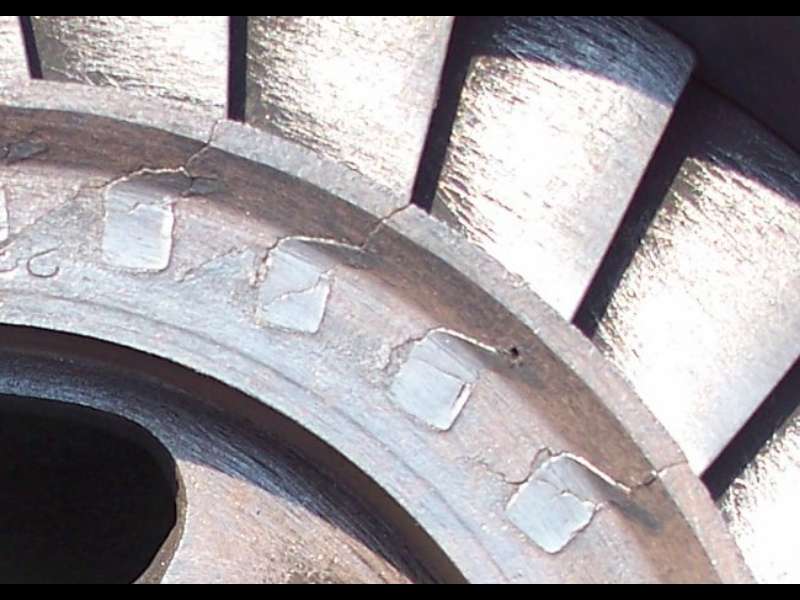
And
then, in the
process of cleaning the gas inlet casing, Jeff discovered that the
nozzle ring was badly cracked. There are little cracks
radiating
out from nearly every spot where the nozzle blades are
inserted. The nozzle ring directs the exhaust
gasses to the
turbine blades and since this is not a rotating part, the only
explanation is that metal fatigue set in after around 50 years of hot
exhaust gasses. Photo 1 shows the nozzle ring and
photo 2
illustrates the cracks. This was an unexpected expense but,
replacement of the ring was the only real option.
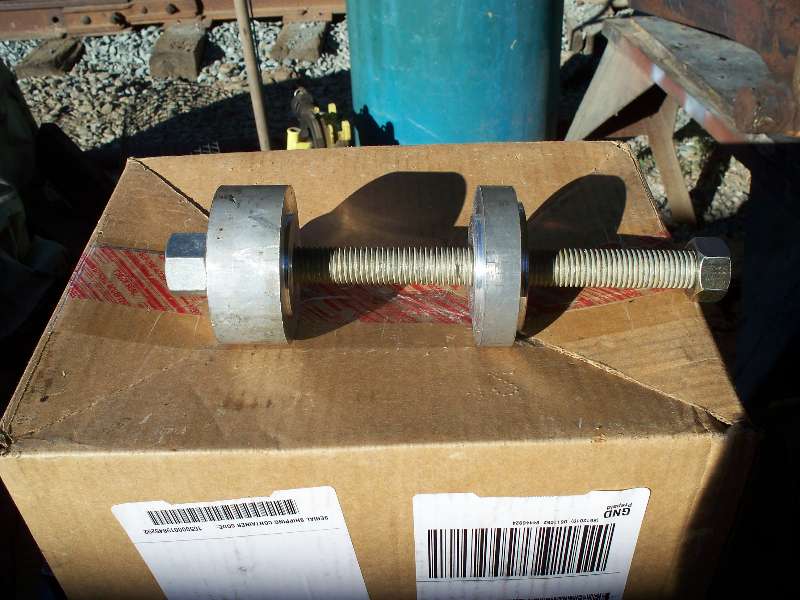
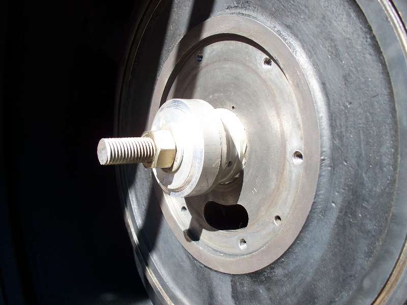
We had to make a special
tool in
order to press the new bearings into place, Photo 1 shows the
tool and photo 2 shows the tool, ready to pull the new bearing into
place. Photo 3 illustrates the bearing, all snugged up
against
the casing, The bearing on the turbine side was pulled into
the
casing in the same manner.
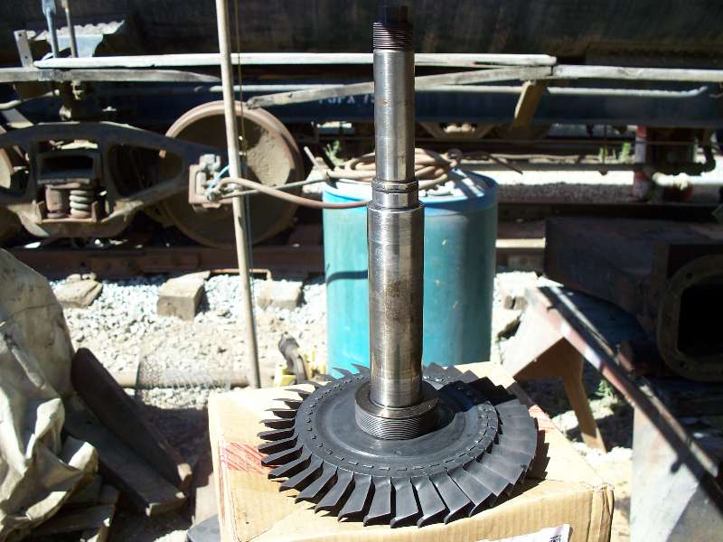
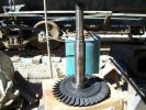
Here are a couple of
photos of the
turbine shaft and its parts. On the bottom is the turbine
which
is driven by the engine exhaust gasses. At the top are the
inducer and impeller which compress the intake air and feed it to the
engine. Because the turbine is exposed to the hot exhaust
gasses,
it is made of stainless steel. The inducer and impeller are
made
of aluminum. All the parts are in remarkably good condition
considering that they are over 40 years old. Yes, the
locomotive
was built in 1955 but the turbo was upgraded by the SP in 1965 when
Alco redesigned the internal parts.
|
|
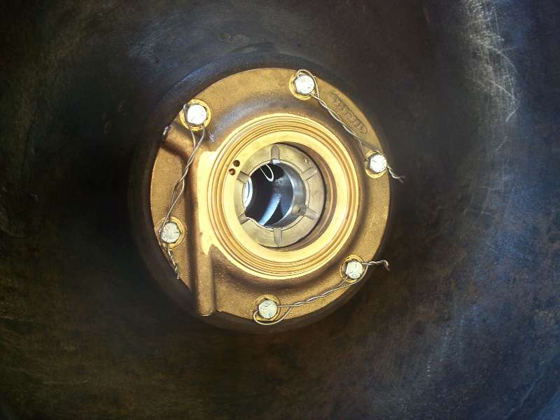
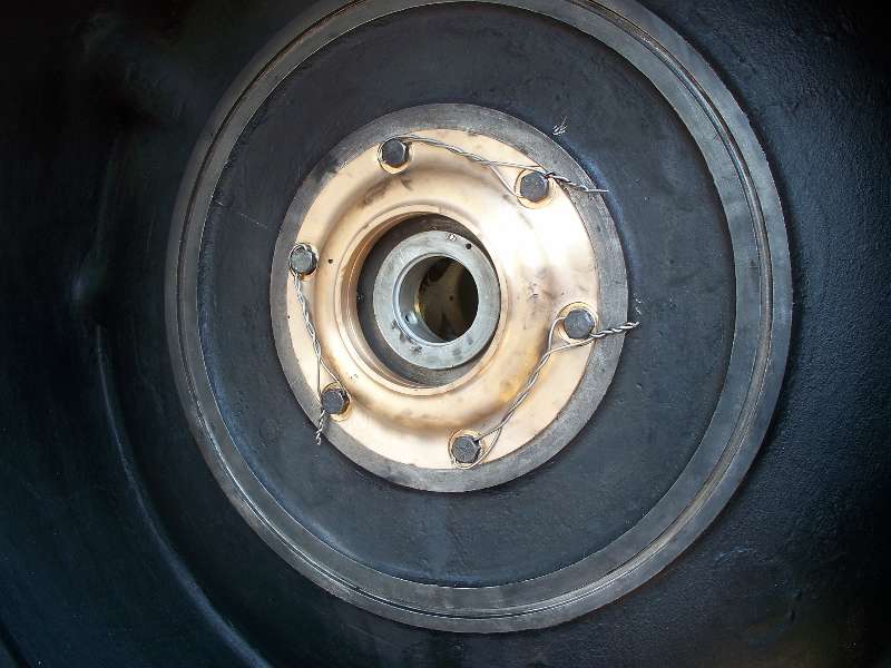
After
the new bearings
were installed, the oil seals were put in place. The one on
the
turbine side had to be carefully spaced out from the casing as it has
to maintain a critical clearance (.004 - .008) to the backside of the
turbine wheel. One all the measurements were confirmed,
stainless
steel safety wire was applied. Photo 1 is the turbine side,
photo
2 is the compressor side and photo 3 is looking down the exhaust at the
turbine and oil seal in place.
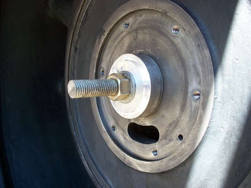
Our
attention now turned to the air side. The inducer and
impeller
were applied to the shaft and the lock nut was torqued to 100 foot
pounds. We decided to spin the turbo with air and with oil
being
poured into the oil line and a strobe tachometer watching the RPM,
managed to get the turbo up to 10, 000 RPM with no unusual noises or
vibration. The bolts that hold the diffuser ring to
the air
inlet casing were torqued and safety wired with stainless steel safety
wire. The casing was hung from 4 long bolts and carefully
positioned into the turbo body. Sixteen 1/2" bolts were
applied
and torqued to 60 foot pounds. We once again spun
the turbo
on air and again found no sign of anything but good news.
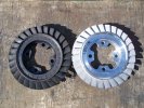
Photo 2
is of the old and new nozzle rings. The brand new $3500 one,
rather than being an
assembly of parts like the old one, is a solid cast stainless steel
part. No wonder it cost so darned much!
It was applied to the gas inlet casing and the assembly
was set in place, again using 4 long studs. Once the bolts
were
in and properly tightened, the turbo was spun up one more time using
air. This completed the turbo overhaul and made it ready to
put
back on the engine.

|
|
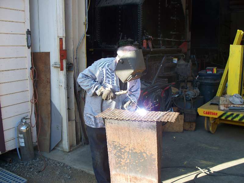
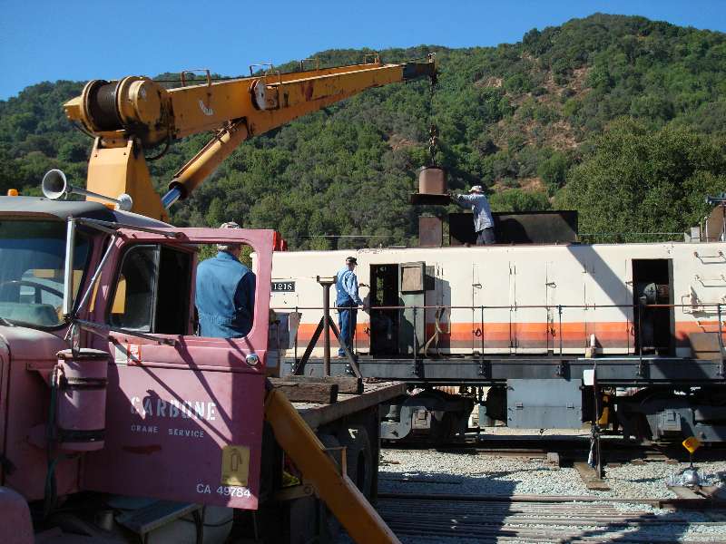
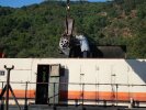
One final detail
needed was the replacement of a missing screen on top of the turbo
outlet. Here I am doing the deed while Jon watches to make
sure I
don't set myself on fire. My leather welding jacket was at
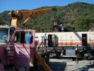
home. The turbo was removed from the temporary stand and Rich
and
Jon lifted the stack back in place. After suitable rigging,
the
turbo and the 1218 were moved to a spot where we could get at them with
our crane. With Rich on the controls, Jon watching our backs
and
me guiding the turbo, it went back into its home with little
problem. Jeff caught one final shot of me guiding the stack
surround into place. After a few hours work connecting things
up,
the 1218 was fired up and the sounds and sights of a running Alco S6
filled Brightside yard, this time without that nasty noise.
Jeff Coker Photo
|
Jeff Coker Photo
|
|