The air
compressor on most
locomotives is driven directly by the diesel engine. The Alco 251
engine has a "extension shaft" bolted to the front end of the engine
crankshaft. The extension shaft has a coupling on its end known
as a Fasts coupling. Half the coupling is attached to the
extension shaft and the other half to the compressor crankshaft.
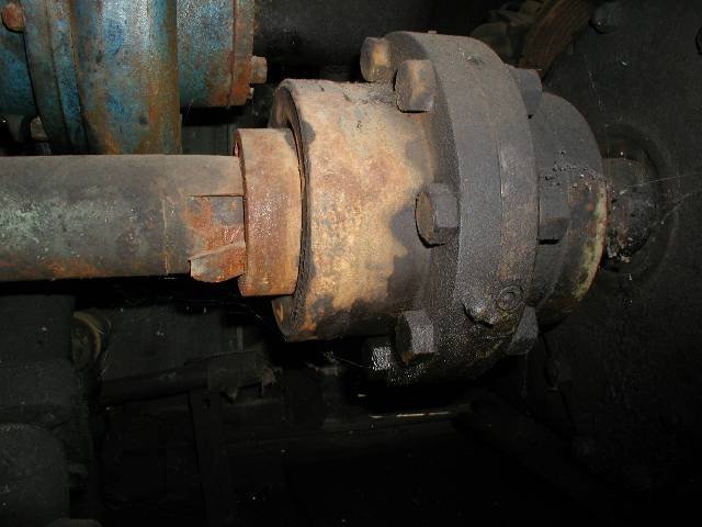
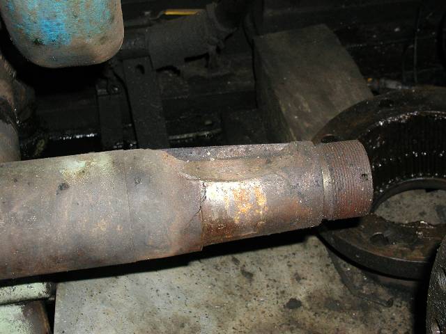
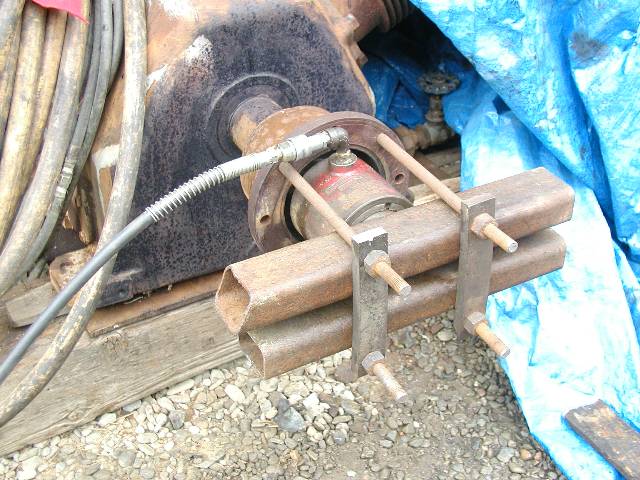
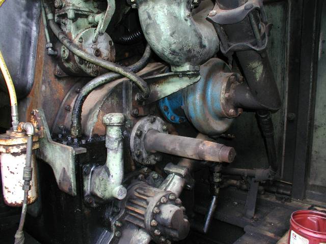
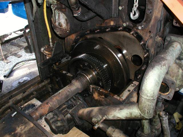
This coupling between the engine and the compressor was severely
damaged
on the 1218 and both the extension shaft and the compressor crankshaft
were nearly destroyed. It appears that the compressor was removed
for some reason and its coupling half was not properly installed after
the compressor was repaired. The coupling came loose and the
shaft was "repaired" by the application of some really ugly weld.
The coupling was put back together and ran that way for some time when
the coupling came loose on both the compressor and the extension
shaft. When we got the 1218, the coupling was only barely holding
together and we knew that a significant repair would have to be
made. The little piece of metal sticking out of the left side of
the coupling in this photo is a hunk of the crankshaft extension that
was torn
loose by the force of the key banging around in its key way.
 |
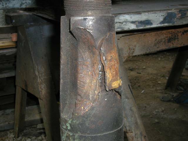
As far as
repairing the damage to the compressor and the engine crankshaft is
concerned, we had several options. They could be built up with
metal and turned down in a lathe and this is the path we though we
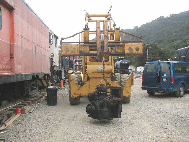
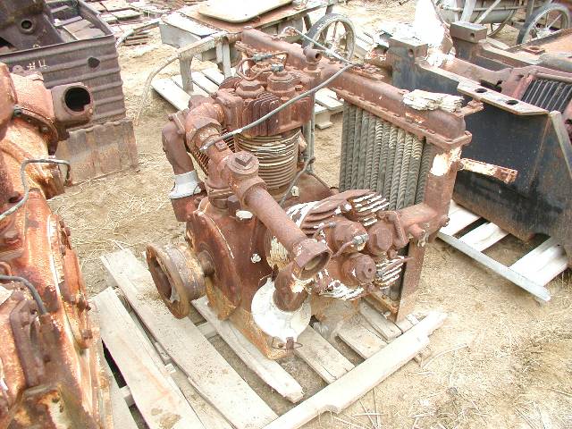
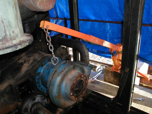
would have to take. We elected to pull the compressor and get
bids on the work. There are no photos of the process of pulling
the compressor out of the 1218. The only one I caught is of it
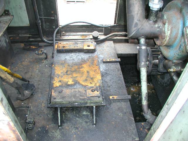
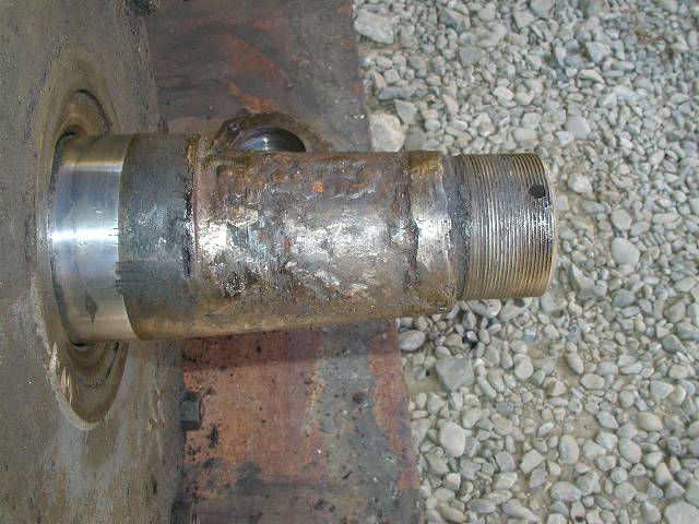
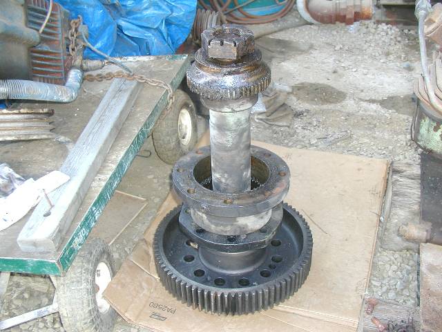
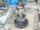
after it was removed. Photo #2 is of the pad where the compressor
sits, #3 is of the damaged compressor crankshaft. #4 and #5 are
of the end
of the engine crankshaft extension.
I got an email
from a fellow who was involved in the scrapping of an S6. He told
me that he had been contacted by author and Southern Pacific historian
Joe Strapac and told that we may be in need of some parts. When I
saw a photo of various engine parts on a pallet, including the
extension shaft, I about had a cow and immediately told him that we
were interested in the shaft. To say that this was a
blessing would be putting it mildly. A purchase was quickly
arranged and the
little jewel came home to Niles Canyon. The acquisition
of this shaft eliminated half of our coupling problem.
 |
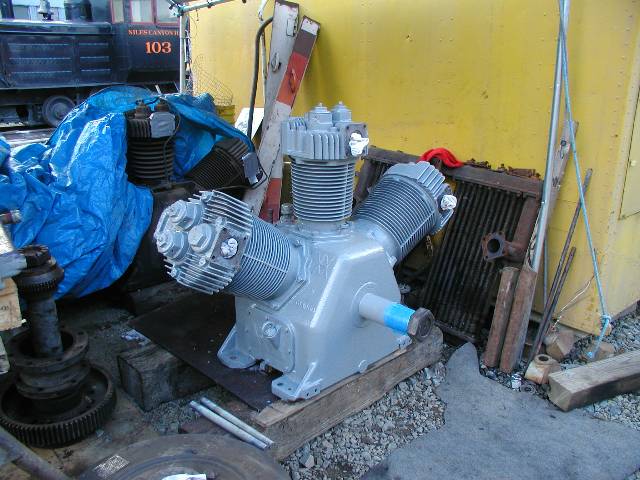
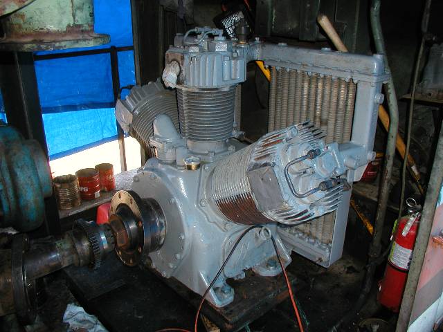
One day, I was
talking with a friend who told me that he knew of a compressor from a
scrapped Alco MRS1 (a military 6 axle locomotive). So Jon, Rich
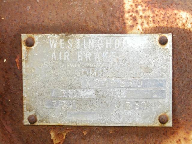
and I took a little trip to have a look. What we found was a
Westinghouse model 3CDC. Except for some piping and the coupling
on one end of the crankshaft, it was exactly what we needed for the
1218. After arrival at Niles Canyon, we proceeded to pull one of
the couplings off. The other coupling was a Fasts, just like the
one on the old compressor.
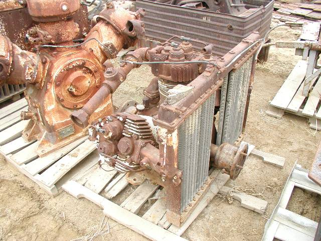
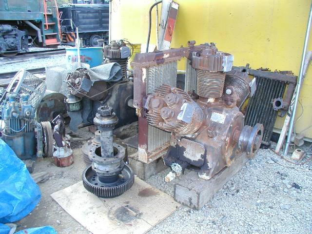
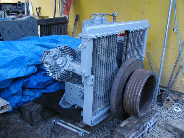
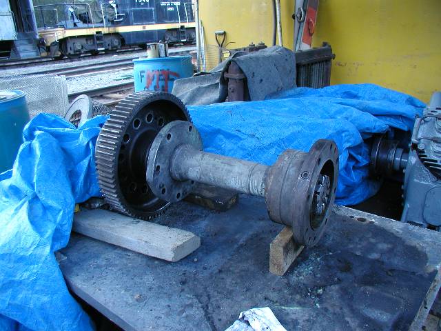
And here are both the shaft and the new
compressor sitting side by
side. We were certainly excited about getting these parts!
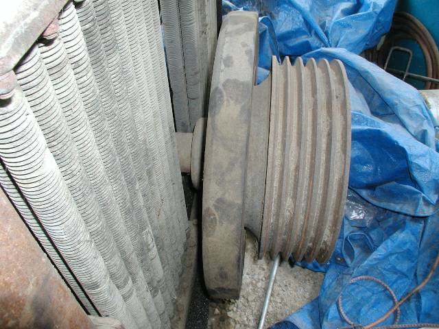
We removed the
pulley and damper from the crank of the old compressor, cleaned up the
new shaft and compressor, put the pulley on the new compressor and were
ready to install the new parts.
It was unknown if
the crankshaft extension shaft could be removed from
the engine without pulling the crankshaft, an operation that we could
not undertake. If the shaft would not come out, it would have to
be repaired in place and we would use the new coupling we got with the
shaft from the scrapped locomotive. The Alco 244 and 251 engines
are very similar. The 244 service manual gives instructions on
how to pull the extension shaft but the 251 manual does not even
mention
the process. After much agonizing, measuring, calculating and
more agonizing, I decided that it would come out. The process
would involve removing some water piping, the water pump, the
turbocharger outlet pipe and the front end gear cover. Photo #1
is the old shaft in place. Photos #2 and #3 are removing the
295 pound water pump.
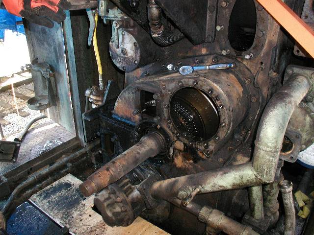
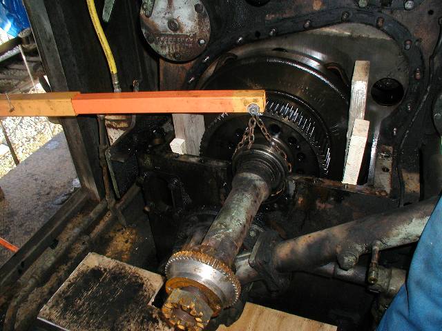
With the piping and the water pump out of the
way, we could attack the gear cover. Once it was removed,
the rest of the shaft and its gear were exposed. At this point,
we could see that the shaft would indeed come out this way. We
rigged our small hydraulic crane to the shaft and pulled the dozen 7/8"
bolts, after blocking the crankshaft vibration damper with wooden
wedges. Once the bolts were out, there was nothing hold the
damper on and if it fell of the crankshaft, we would have a real
problem on our hands. With some gentle persuasion, the old shaft
came out quite easily.
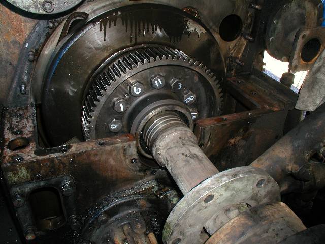
The replacement shaft was rigged in the same
manner and carefully
positioned into its new home. The numbers painted on the bolt
heads are the sequence numbers for the tightening pattern. It is
critical that the shaft bolts be tightened evenly so that the shaft
will not wobble at the coupling end. This wobble is called
"runout" and cannot exceed .006" (6 1000's of an inch). When we
measured the runout after torquing the bolts to 450 foot pounds, the
runout measured a very nice .002". After this, the cover
went on and the pump went back in.
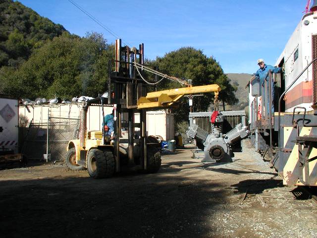
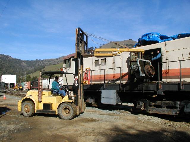
Next on the
agenda was putting the new compressor in. It weights roughly 1500
pounds so some care was required. With Jon on the forklift and
Rich and I guiding the compressor, the job was quickly done.
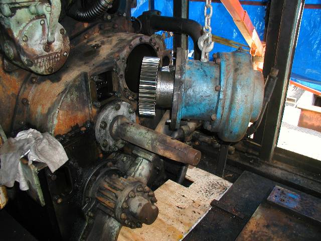
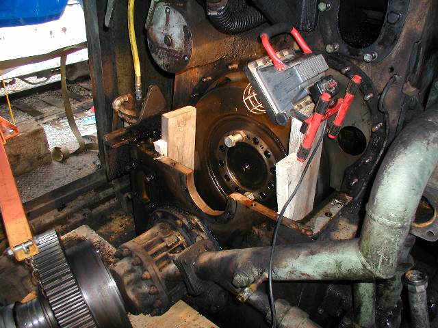
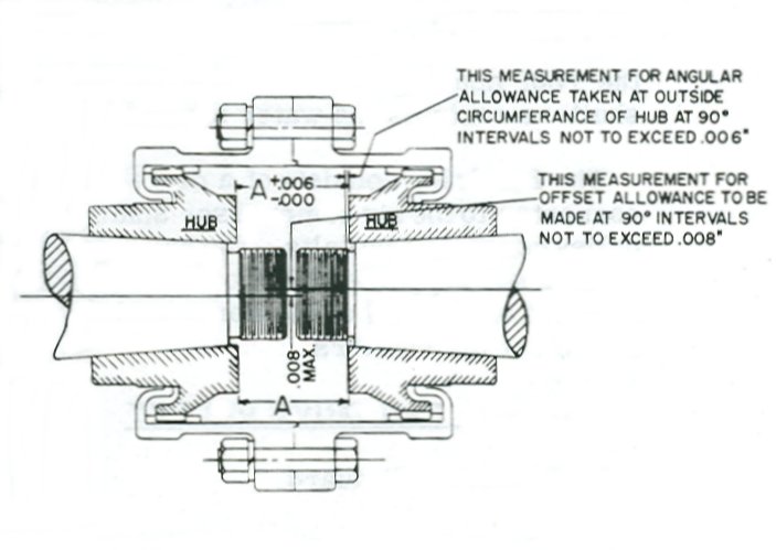
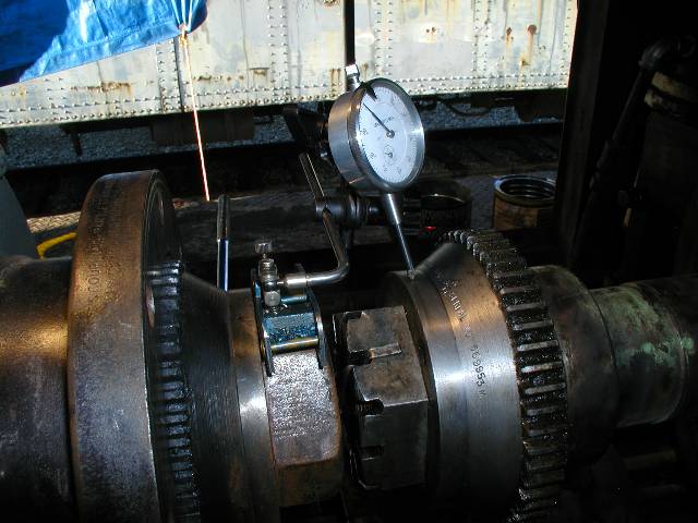
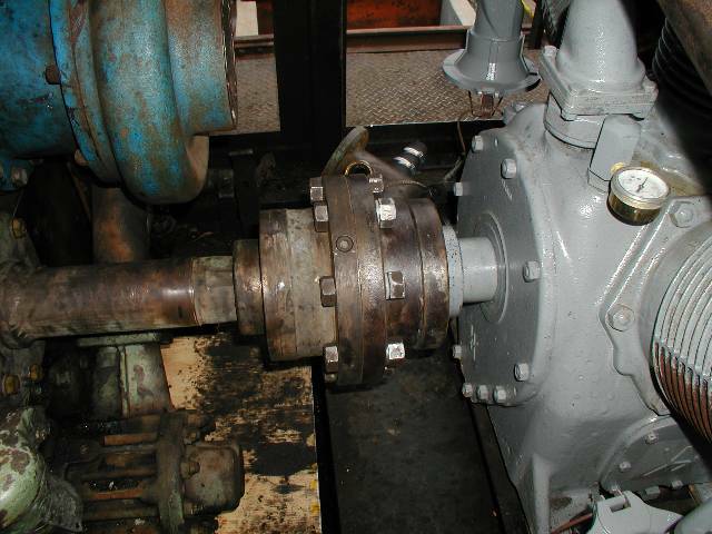
The compressor
and the engine crankshaft have to be carefully aligned, both
horizontally and vertically. Photo #2 shows a dial indicator
attached to a magnetic base which is sitting on the nut of the
compressor shaft. The indicator shaft is resting against the hub
of the engine crankshaft coupling. By rotating the compressor, we
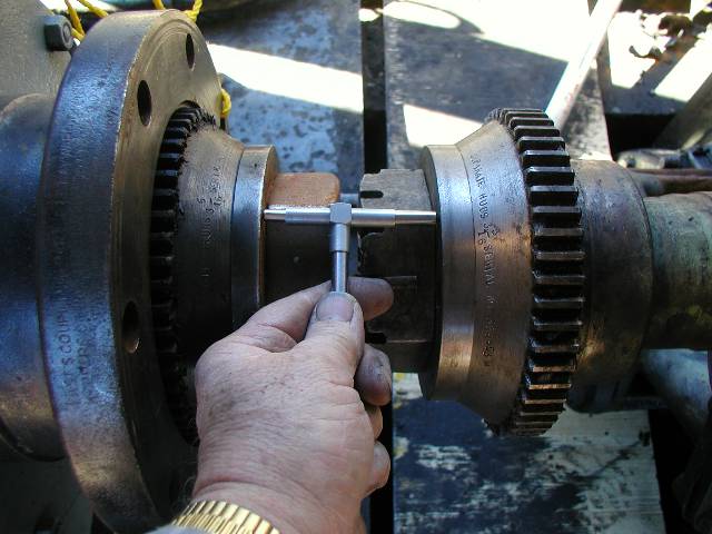
can read the offset between the two shafts. Photo 3 illustrates
the taking of the measurement that indicates if the shafts are
operating in the same plane. The difference between this
measurement and another taken 180 degrees around the coupling faces can
be a maximum of only .006". These are only a couple of
the measurements to be made during the process of
alignment. Changes to the alignment are made by putting
steel shims under the compressor mounting feet and moving the
compressor around on its mounting pad.
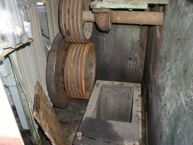
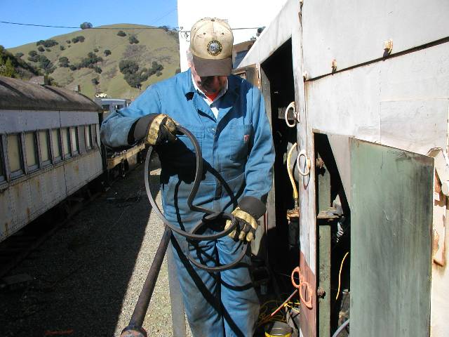
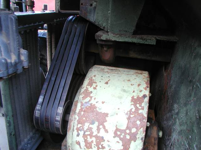
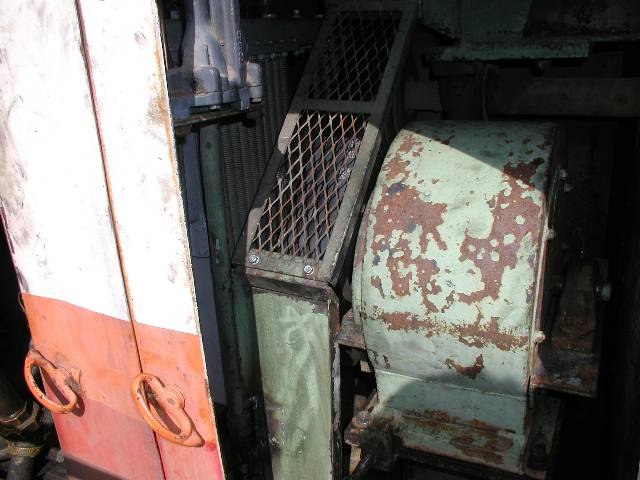
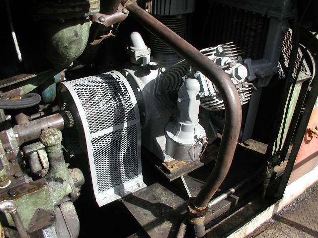
Photo #1 illustrates the top of the front
traction motor cooling air
duct where the blower resides. The lower pulley is on the front
of
the compressor and the upper is on the engine cooling fan shaft.
The pulley on the front end of the air compressor drives both the
blower and the engine cooling fan. Jon
and Rich are getting ready to muscle the blower back in its location
and Rich is seen uncoiling one of the 5 fan belts. At last, all
the belts are on and correctly tightened. The protective
coverings for the belts was then added.
The final
operations were to put all the various pipes back on the engine,
connect and lubricate the coupling and then install the protective
shield over the coupling and shafts.
|